The simplest radio circuits. DIY radio circuits for home. Design of the finished structure
Electrical circuits for beginners, amateurs and professionals
Welcome to the Radio Circuits section! This is a separate section of the Radio Amateurs Site, which was created specifically for those who are comfortable with a soldering iron, are used to doing everything themselves, and it is dedicated exclusively to electrical circuits.
Here you will find circuit diagrams of various topics such as For self-assembly by beginner radio amateurs, and for more experienced radio amateurs, for those for whom the word RADIO has long become not just a hobby but a profession.
In addition to circuits for self-assembly, we also have a fairly large (and constantly updated!) database of electrical circuits for various industrial electronics and household appliances - circuits for televisions, monitors, radios, amplifiers, measuring instruments, washing machines, microwaves, and so on.
Especially for repair workers, we have a “Datasheets” section on our website, where you can find reference information on various radio elements.
And if you need any scheme and want it download, then we have everything here free, no registration, no SMS, no file sharing and other surprises
If you have questions or haven’t found what you were looking for, come to our FORUM and let’s think together!!
To make it easier to find the necessary information, the section is divided into categories
|
Schemes for beginners This section contains simple circuits for beginner radio amateurs. |
Light and music
light devices x effects: flashing lights, color music, stroboscopes, automatic switching of garlands and so on. Of course, you can assemble all the circuits yourself materials in category |
Power supply circuits
Any electronic equipment needs power. This category is dedicated to power supplies. materials in category |
|
Electronics in everyday life This category presents diagrams of devices for household use: rodent repellers, various alarms, ionizers, and so on... |
Antennas and Radios Antennas (including homemade ones), antenna components, as well as radio receiver circuits for self-assembly |
Spy things
This section contains diagrams of various "spy" devices - radio bugs, phone jammers and listeners, radio bug detectors |
|
Auto-Moto-Velo electronics
Schematic diagrams of various auxiliary devices to cars: chargers, direction indicators, headlight control and so on |
Measuring instruments
Electrical circuit diagrams of measuring instruments: both home-made and industrial production materials in category |
Domestic technology of the 20th Century
A selection of electrical circuit diagrams of household radio equipment produced in the USSR materials in category |
|
LCD TV circuits
Electrical circuit diagrams of LCD TVs (LCD) materials in category |
Programmer circuits
Schemes of various programmers materials in category |
Audio
Circuits of sound-related devices: transistor and microcircuit amplifiers, pre-amplifiers and tube amplifiers, sound conversion devices materials in category |
|
Monitor circuits
materials in category |
Schemes of car radios and other car audio equipment
A selection of car audio circuits: car radios, amplifiers and car TVs |


 Schematic diagrams of various monitors: both old kinescopes and modern LCDs
Beginner radio amateurs who are interested in independently assembling circuits and repairing various electronic devices are lost in a sea of numerous terms and details. Meanwhile, you can give a number of tips on what knowledge is needed in the first place, what devices to use, how to navigate when choosing circuit elements.
Required knowledge
For radio amateurs it is very important:
- know and understand the basic laws of electrical engineering;
- be able to navigate the schemes;
- clearly define the role of each element in the diagram and represent visually how it looks.
Important! Theoretical knowledge must be constantly reinforced by practice.
Tools and devices
To assemble amateur radio circuits and home-made structures, you must have the following tools:
- Soldering iron, the power of which must be chosen average - no more than 40 watts. More advanced craftsmen are thinking about purchasing a soldering station;
- Side cutters. Not too massive tool for working with radio devices;

- Tin-lead solder exists in the form of a wire.
Important! Among all devices, the main, and often the only one, is a digital multimeter or analog tester, through which you can measure all the main parameters of the circuit.
Before you start assembling simple and interesting do-it-yourself radio circuits, you can practice dismantling old radio equipment. At the same time, a practical skill is formed in soldering work.
- In ancient televisions with lamps, a quite suitable thing is a supply transformer. It can be used in many DIY radios. For example, to assemble a charger for a car battery or a power supply unit for a sound amplifier. The main thing is to know its technical data;
- In obsolete radio electronic devices: television equipment, video recorders, conventional tape recorders, there are whole microcircuits ready for use. An example would be an audio amplifier whose circuit is constructed by simply assembling components, without etching on printed circuit boards, etc.;
- The tone control is also used in finished form. At the same time, the assembled sound amplifier will receive new options: the ability to control the low-frequency and high-frequency ranges, change the balance in stereo speakers;
- Basically, all devices manufactured by radio amateurs operate on five-, nine- and twelve-volt power supplies. Such power supplies from old equipment will be the most useful.
As cases for circuits, you can use any improvised designs or buy ready-made ones, of different sizes and shapes. Shrouds from non-working devices are often used for new radio homemade products.
A non-working PSU from a computer is very valuable, where it comes from:
- many radio components: transistors, capacitors, diodes, resistances that are useful for assembled devices;
- cooling radiators are an important accessory for high power transistors;
- good wires;
- the hull itself is a great place to place new structures.

Circuit Assembly Methods
- Hanging installation. Simple soldering of components in accordance with the developed scheme. Soldered nodes can be installed on supporting platforms. The method is suitable for constructing radio circuits from a small number of parts;
- Mounting on a printed circuit board - a textolite platform on which foil tracks are made as connecting conductors.
The second method is divided into several options:
- Mechanical. Cutting tracks with a sharp object to exclude contact connections in unnecessary places;
- Chemical. With the help of varnish or paint on the foil, you need to draw the required scheme. Then immerse in a special composition - a solution of ferric chloride. After processing, a wiring corresponding to the drawing will be obtained, and all areas without varnish will be removed by dissolution;
- Laser ironing.
What schemes to start with
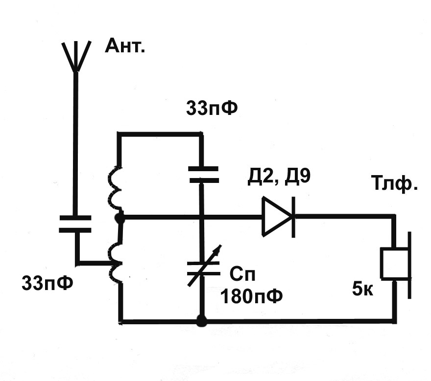
The classic start for radio amateurs is to make a simple detector receiver. The circuit contains a small number of components, and its assembly will be within the power of everyone. Then you can supplement the device with an audio amplifier using transistors. With the advent of experience and understanding, work with microcircuits begins.
A large number of interesting and very simple radio homemade options with a description of the details, the provision of diagrams are on the RadioKot website. You can, for example, assemble color music, pulsed clock illumination, a stereo transmitter, and much more. There are also useful forums where you can clarify complex issues, chat with experienced craftsmen.
As skills are acquired, interest in assembling complex devices will increase. Radio-electronic homemade products are one of the most exciting activities for people of all ages.
Video
You can make the simplest electronic circuits for everyday use with your own hands, even without deep knowledge in electronics. In fact, at the household level, radio is very simple. Knowledge of the elementary laws of electrical engineering (Ohm, Kirchhoff), the general principles of operation of semiconductor devices, skills in reading circuits, the ability to work with an electric soldering iron is enough to assemble a simple circuit.
Ham radio workshop
No matter how complex the scheme would have to be, you must have a minimum set of materials and tools in your home workshop:
- Side cutters;
- Tweezers;
- Solder;
- Flux;
- Circuit boards;
- Tester or multimeter;
- Materials and tools for the manufacture of the body of the device.
You should not purchase expensive professional tools and devices to begin with. An expensive soldering station or digital oscilloscope is of little help to a beginner radio amateur. At the beginning of the creative path, the simplest instruments are quite enough, on which you need to hone your experience and skills.

Where to start
Do-it-yourself radio circuits for the home should not exceed the level of complexity that you own, otherwise it will only mean wasted time and materials. With a lack of experience, it is better to limit yourself to the simplest schemes, and as you accumulate skills, improve them, replacing them with more complex ones.
Usually, most of the literature from the field of electronics for beginner radio amateurs gives a classic example of making the simplest receivers. This is especially true of classical old literature, in which there are not so many fundamental errors in comparison with contemporary literature.
Note! These schemes were designed for the huge power of transmitting radio stations in the past. Today, transmitting centers use less power to transmit and try to get into the shorter wavelength range. Do not waste time trying to make a working radio using the simplest circuit.
Radio circuits for beginners should include a maximum of a couple of active elements - transistors. So it will be easier to understand the operation of the circuit and increase the level of knowledge.
What can be done
What can be done so that it is not difficult and can be used in practice at home? There can be many options:
- apartment call;
- Christmas tree garlands switch;
- Backlight for modding the computer system unit.

Important! Appliances to be powered by household AC power should not be designed unless there is sufficient experience. It is dangerous for life and for others.
Pretty simple circuits have amplifiers for computer speakers, made on specialized integrated circuits. Devices assembled on their basis contain a minimum number of elements and practically do not require adjustment.
You can often find circuits that need elementary alterations, improvements that make it easier to manufacture and configure. But this should be done by an experienced master in order to make the final version more accessible to a beginner.
On what to build
Most of the literature recommends designing simple circuits on circuit boards. At present, this is quite easy. There is a wide variety of circuit boards with different hole patterns and printed tracks.
The principle of installation is that the parts are installed on the board in free places, and then the necessary conclusions are connected to each other by jumpers, as indicated in the circuit diagram.

With due care, such a board can serve as the basis for many circuits. The power of the soldering iron for soldering should not exceed 25 W, then the risk of overheating the radio elements and printed conductors will be minimized.
The solder should be fusible, such as POS-60, and it is best to use pure pine rosin or its solution in ethyl alcohol as a flux.
Highly qualified radio amateurs can design a printed circuit board pattern themselves and execute it on foil material, on which radio elements are then soldered. The design developed in this way will have optimal dimensions.
Design of the finished structure
Looking at the creations of beginners and experienced craftsmen, one can come to the conclusion that the assembly and adjustment of the device is not always the most difficult part of the design process. Sometimes a properly working device remains a set of parts with soldered wires, not closed by any case. At present, you can no longer be puzzled by the manufacture of the case, because on sale you can find all kinds of sets of cases of any configuration and dimensions.

Before you start manufacturing the design you like, you should fully think through all the stages of the work: from the availability of tools and all radio elements to the version of the case. It will be completely uninteresting if in the process of work it turns out that one of the resistors is missing, and there are no replacement options. The work is best done under the guidance of an experienced radio amateur, and, in extreme cases, periodically monitor the manufacturing process at each stage.
Video
Those who are engaged in radio electronics at home are usually very inquisitive. Amateur radio circuits and homemade products will help you find a new direction in creativity. Perhaps someone will find an original solution to a particular problem. Some homemade products use ready-made devices, connecting them in various ways. For others, you need to completely create the circuit yourself and make the necessary adjustments.
One of the easiest crafts. More suitable for those who are just starting to tinker. If you have an old but working cell phone with a button to turn on the player, you can use it, for example, to make a doorbell to your room. Benefits of this call:

First you need to make sure that the selected phone is capable of producing a sufficiently loud melody, after which it must be completely disassembled. Basically, the parts are fastened with screws or brackets, which are carefully bent. When disassembling, you will need to remember what goes for what, so that later you can reassemble everything.
The player's power button is soldered on the board, and two short wires are soldered instead. These wires are then glued to the board so as not to tear off the solder. The phone is going. It remains to connect the phone to the call button through a two-wire wire.
Homemade for cars
Modern cars are equipped with everything you need. However, there are times when homemade devices are simply necessary. For example, something broke, given to a friend, and the like. Then the ability to create electronics with your own hands at home will be very useful.
The first thing you can intervene in without fear of damaging the car is the battery. If at the right time charging for the battery was not at hand, you can quickly assemble it yourself. This will require:

The transformer from the tube TV is ideal. Therefore, those who are fond of homemade electronics never throw away electrical appliances in the hope that they will someday be needed. Unfortunately, two types of transformers were used: with one and with two coils. To charge the battery at 6 volts, anyone will go, and for 12 volts, only with two.
The wrapping paper of such a transformer shows the winding leads, the voltage for each winding, and the operating current. To power the filaments of electronic lamps, a voltage of 6.3 V with a large current is used. The transformer can be redone by removing unnecessary secondary windings, or left as is. In this case, the primary and secondary windings are connected in series. Each primary is designed for a voltage of 127 V, therefore, by combining them, they get 220 V. The secondary ones are connected in series to get 12.6 V at the output.
Diodes must be capable of withstanding at least 10 A. Each diode requires a heat sink of at least 25 square centimeters. They are connected to a diode bridge. Any electrical insulating plate is suitable for fastening. A 0.5 A fuse is included in the primary circuit, and 10 A in the secondary circuit. The device does not tolerate a short circuit, therefore, when connecting the battery, the polarity must not be confused.
Simple heaters
In the cold season, it may be necessary to warm up the engine. If the car is parked where there is electricity, this problem can be solved with a heat gun. For its manufacture you will need:
- asbestos pipe;
- nichrome wire;
- fan;
- switch.

The diameter of the asbestos pipe is selected according to the size of the fan to be used. The performance of the heater will depend on its power. Pipe length is everyone's preference. You can assemble a heating element and a fan in it, you can only have a heater. When choosing the latter option, you will have to think about how to let the air flow to the heating element. This can be done, for example, by placing all components in a sealed enclosure.
Nichrome wire is also selected by the fan. The more powerful the latter, the larger diameter nichrome can be used. The wire is twisted into a spiral and placed inside the pipe. Bolts are used for fastening, which are inserted into pre-drilled holes in the pipe. The length of the spiral and their number are chosen empirically. It is desirable that the coil does not heat up red-hot when the fan is running.
The choice of fan will determine how much voltage you need to apply to the heater. When using a 220 V electric fan, you will not need to use an additional power source.
 The entire heater is connected to the network through a cord with a plug, but it must have its own switch. It can be either just a toggle switch or an automatic one. The second option is more preferable, it allows you to protect the overall network. To do this, the tripping current of the machine must be less than the tripping current of the room machine. A switch is also needed to quickly turn off the heater in case of malfunctions, for example, if the fan does not work. Such a heater has its drawbacks:
- harm to the body from asbestos pipes;
- noise from a running fan;
- the smell of dust falling on a heated coil;
- fire hazard.
Some problems can be solved by applying another homemade product. Instead of an asbestos pipe, you can use a coffee can. So that the spiral does not close on the jar, it is attached to a textolite frame, which is fixed with glue. A cooler is used as a fan. To power it, you will need to assemble another electronic device - a small rectifier.
Homemade products bring to the one who deals with them not only satisfaction, but also benefit. With their help, you can save electricity, for example, by turning off electrical appliances that you forgot to turn off. For this purpose, you can use a time relay.
The easiest way to create a timing element is to use the charge or discharge time of a capacitor through a resistor. Such a chain is included in the base of the transistor. The diagram will require the following details:
- high capacity electrolytic capacitor;
- p-n-p type transistor;
- electromagnetic relay;
- diode;
- variable resistor;
- fixed resistors;
- DC source.

First you need to determine what current will be switched through the relay. If the load is very powerful, you will need a magnetic starter to connect it. The starter coil can be connected via a relay. It is important that the relay contacts can operate freely without sticking. According to the selected relay, a transistor is selected, it is determined with what current and voltage it can work. You can focus on KT973A.
The base of the transistor is connected through a limiting resistor to a capacitor, which, in turn, is connected through a bipolar switch. The free contact of the switch is connected through a resistor to the minus power supply. This is necessary to discharge the capacitor. The resistor acts as a current limiter.
The capacitor itself is connected to the positive bus of the power supply through a variable resistor with a large resistance. By selecting the capacitance of the capacitor and the resistance of the resistor, you can change the delay time interval. The relay coil is shunted by a diode that turns on in the opposite direction. This circuit uses KD 105 B. It closes the circuit when the relay is de-energized, protecting the transistor from breakdown.
 The scheme works as follows. In the initial state, the base of the transistor is disconnected from the capacitor, and the transistor is closed. When the switch is turned on, the base is connected to the discharged capacitor, the transistor opens and supplies voltage to the relay. The relay operates, closes its contacts and supplies voltage to the load.
The capacitor begins to charge through a resistor connected to the positive terminal of the power supply. As the capacitor charges, the base voltage begins to rise. At a certain voltage value, the transistor closes, de-energizing the relay. The relay disconnects the load. To make the circuit work again, you need to discharge the capacitor, for this the switch is switched.
 WITH where to start study of radio electronics? How to build your first electronic circuit? Is it possible to quickly learn to solder? It is for those who ask such questions that the section has been created "Start"
.
WITH where to start study of radio electronics? How to build your first electronic circuit? Is it possible to quickly learn to solder? It is for those who ask such questions that the section has been created "Start"
.
N and pages This section publishes articles about what any beginner in radio electronics should know first of all. For many radio amateurs, electronics, which was once just a hobby, eventually grew into a professional environment of activity, helped in finding a job, in choosing a profession. Taking the first steps in the study of radio elements, circuits, it seems that all this is terribly complicated. But gradually, as knowledge accumulates, the mysterious world of electronics becomes more understandable.
E if You have always been interested in what is hidden under the cover of an electronic device, then you have come to the right place. Perhaps a long and exciting journey in the world of radio electronics will begin for you from this site!
To go to the article of interest, click on the link or thumbnail image next to the brief description of the material.
Measurements and measuring equipment
Any radio amateur needs a device with which to check radio components. In most cases, electronics enthusiasts use a digital multimeter for this purpose. But far from all elements can be checked with them, for example, MOSFET transistors. Your attention is invited to an overview of the universal ESR L / C / R tester, which can also be used to test most semiconductor radio elements.
The ammeter is one of the most important instruments in the laboratory of a beginner radio amateur. With it, you can measure the current consumed by the circuit, set the operating mode of a particular node in an electronic device, and much more. The article shows how in practice you can use an ammeter, which is mandatory in any modern multimeter.
Voltmeter - a device for measuring voltage. How to use this device? How is it indicated on the diagram? You will learn more about this from this article.
From this article, you will learn how to determine the main characteristics of a pointer voltmeter by the symbols on its scale. Learn to read readings from the scale of a pointer voltmeter. A practical example awaits you, and you will also learn about an interesting feature of a pointer voltmeter that you can use in your homemade products.
How to test a transistor? This question is asked by all novice radio amateurs. Here you will learn how to test a bipolar transistor with a digital multimeter. The transistor test technique is shown on specific examples with a large number of photographs and explanations.
How to test a diode with a multimeter? Here is a detailed description of how you can determine the health of the diode with a digital multimeter. A detailed description of the testing technique and some "tricks" of using the diode test function of a digital multimeter.
From time to time I am asked the question: "How to check the diode bridge?". And, it seems, I have already talked about the method of checking all kinds of diodes in sufficient detail, but I did not consider the method of checking the diode bridge in a monolithic assembly. Let's fill this gap.
If you do not yet know what a decibel is, then we recommend that you slowly read the article about this entertaining unit of measurement of levels. After all, if you are engaged in radio electronics, then sooner or later life will make you understand what a decibel is.
Often in practice, it is required to convert microfarads to picofarads, millihenries to microhenries, milliamps to amperes, etc. How not to get confused when recalculating the values of electrical quantities? This will help the table of factors and prefixes for the formation of decimal multiples and submultiples.
In the repair process and in the design of electronic devices, it becomes necessary to check capacitors. Often, seemingly serviceable capacitors have defects such as electrical breakdown, open circuit, or loss of capacitance. Capacitors can be checked using widely used multimeters.
Equivalent series resistance (or ESR) is a very important capacitor parameter. This is especially true for electrolytic capacitors operating in high-frequency pulse circuits. Why is EPS dangerous and why is it necessary to take into account its value when repairing and assembling electronic equipment? You will find answers to these questions in this article.
The power dissipation of a resistor is an important parameter of a resistor that directly affects the reliability of this element in an electronic circuit. The article talks about how to estimate and calculate the power of a resistor for an application in an electronic circuit.
Workshop of a beginner radio amateur
How to read circuit diagrams? This question is faced by all novice electronics lovers. Here you will learn how to learn to distinguish the designations of radio components on circuit diagrams and take the first step in understanding the design of electronic circuits.
 Do-it-yourself power supply. The power supply is an indispensable attribute in the radio amateur's workshop. Here you will learn how to assemble an adjustable power supply with a switching regulator yourself.
The most popular device in the laboratory of a beginner radio amateur is an adjustable power supply. Here you will learn how to assemble an adjustable 1.2 ... 32V power supply based on a ready-made DC-DC converter module with a minimum of effort and time.